
Tata truck service & repair manuals PDF free download
Diagnostic manual Tata 1.4 and 2.2 Common rail engines
Fault Codes List Download
You will most likely need an Indian Scanner to read the errors. Most of our scanners do not see the ECM. If you have a Bosch EDC15VM engine control unit, perhaps flashing it for further correct reading will help. You can still use the Texa Navigator txts Truck & Launch X-431 Diagun scanner
ТАТА LPT-613 Service Manual Download
LPTA 713S 4x4TRUCK Download
Tata Ace Zip Brochure. Download
Tata LPK 2516 C EURO-II Parts list Download
Tata LPK2518HD-38-BS3-G1150-MT-ERGO-AC-14BOX Parts list Download
TATA LPT 1618-52, 697 TCIC Euro 3 Part List Download
TATA LPT 613 Operator’s Service Book Download
Tata Xenon Owners Manual Download
TATA-613 Wiring Diagram Download
WIRING DIAGRAMS TATA 613
FUSE BOX & RELAY COVER TATA 613

Bulb specifications TATA 613

Wire color designations for basic chassis wiring diagrams
- B Black
- Br Brown
- G Green
- Gy Gray
- L Blue
- O Orange
- P Pink
- R Red
- W White
- Y Yellow
- V purple
- Lg Light green
- Sb Sky blue

The scheme of starting, charging the battery and the solenoid device for blocking the engine of the base chassis with a voltage of the on-board network of 12 V:
1. Storage battery (12V).
2. Starter relay.
3. Starter.
4. "Mass".
5. Generator.
6. Fuse for relay and engine blocking indicator.
7. Diode.
8. Wiring harness of the instrument cluster.
9. Engine blocking relay.
10. Solenoid of the engine blocking device.
11. Temperature gauge sensor.
12. "Weight" of the body.
13. Control lamp of the battery discharge.
14. Temperature indicator.
a - from the steering lock / ignition switch.
Note: MWH is Main Wire Harness, TWH is Rear Wire Harness, EWH is Engine Wire Harness.
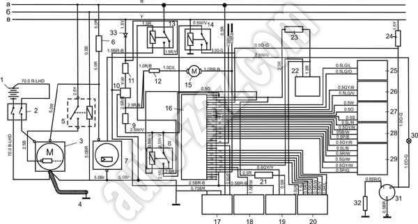
The scheme of starting, charging the battery and controlling the engine of the basic chassis of the bus with a voltage of the on-board network of 24 V (EURO III):
1. Storage battery (2 pcs. 12 V).
2. Battery power switch.
3. Starter.
4 . "Weight".
5 . Starter relay.
6. Power supply circuit protector (60 A).
7. Generator.
8. Relay for engine control unit I (12 V).
9. Fuse for the engine control unit (15 A).
10. Voltage converter.
11. Fuse for voltage converter (15 A).
12. Fuel pump fuse (5 A).
13. Latching relay.
14. Relay for engine control unit II.
15. Fuel pump.
16. Engine control unit (ECU).
17. Diagnostic connector.
18. Solenoid of the engine stop system.
19. Vehicle speed sensor.
20. Pump.
21. Fuse for the vehicle speed sensor (5 A).
22. Timer solenoid.
23. Timer solenoid fuse (10 A).
24. Fuse for the temperature indicator (5 A).
25. Coolant temperature sensor.
26. Needle displacement sensor.
27. Crankshaft speed sensor.
28. High pressure sensor.
29. Module of pedals and consumers of electricity.
30. Battery charge indicator.
31. Temperature indicator.
32. Temperature sensor.
33. Diode.
a - to the "+" terminal of the storage battery (30);
b - to the ignition switch (ACC);
c - to the ignition switch (15).
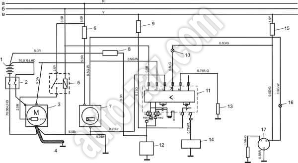
Wiring diagram of the engine control unit of the base chassis with on-board supply voltage 24 V (EURO III):
1. Storage battery (2 pcs. 12 V).
2. Battery power switch.
3. Starter.
4. "Mass".
5. Starter relay.
6. Power supply fuse (60 A).
7. Generator.
8. Glow plug fuse (80 A).
9. Fuse for engine stop system (5 A).
10. Indicator of pressure and temperature of the engine.
11. Engine control unit.
12. Glow plug.
13. Temperature sensor.
14. Solenoid spark plug.
15. Fuse for the temperature gauge and the engine pressure and temperature indicator (5 A).
16. Battery charge indicator.
17. Temperature indicator.
a - to the "+" terminal of the storage battery (30);
b - to the ignition switch (ACC);
c - to the ignition switch (15).