
Komatsu Forklift Service Repair Manuals. Error Codes
Forklift Service Manuals Free Download
Komatsu CX20 Service Manual Download
Komatsu CX Forklift Truck S/N 130001A Service Manual Download
Komatsu FD-, FG-series Forklifts Shop Manual Download
Komatsu Forklift Hydraulic System – Service Manual Part 2 Download
Komatsu Forklift Parts Catalog Download
FG10/15/18-20
FG15H/18H-20
FD10/15/18-20
FG20/25/30-16
FG20H/25H/-16
FG20N/25N/30N-16
FG35A-16
FD20/25/30-16
FD20H/25H/30H-16
FD20N/25N/30N-16
FD35A-16
Komatsu FD-, FG-series Forklifts Shop Manual Download
Komatsu Fault Codes
Malfunction code (ALA)
|
Code |
Fault description |
|
ALA-5206 |
Crank switch is turned ON while the lift control lever is in a non-neutral position |
|
ALA-5207 |
Crank switch is turned ON while the tilt lever is in a non-neutral position. |
|
ALA-5208 |
The starter switch is in the ON position while the ATT 1 implement control lever 1 is in a non-neutral position. |
|
ALA-5209 |
The start switch is in the ON position while the ATT 2 implement control lever 2 is in a position other than neutral |
|
ALA-5210 |
The start switch is in the ON position while the ATT 3 implement control lever 3 is in a position other than neutral |
|
ALA-5229 * |
The automatic tilt adjustment function is disabled before or after the stop position. |
|
ALA-5255 * |
Improper operation of the automatic horizontal tilt adjustment function. 1. Move the tilt control lever in the reverse direction. 2. Activating the horizontal tilt button while the tilt control is in the horizontal position. 3. Activation of the automatic horizontal tilt function while the load is on the machine. |
* The machine is equipped with an automatic horizontal tilt adjustment function
Error code (ERR)
|
Code |
The nature of the malfunction |
|
ERR-3082 |
Fault in the communication channel between the (right) travel controller and the (left) travel controller. |
|
ERR-3084 |
Malfunction of the communication channel between the controller (right) travel and the controller of loading and unloading operations |
|
ERR-3281 |
Malfunction of the communication channel between the controller (right) stroke and controller (left) stroke |
|
ERR-3284 |
Malfunction of the communication channel between the controller of loading and unloading operations and the controller (left) of the course |
|
ERR-5081 |
Malfunction of the communication channel between the controller (right) travel and the controller of loading and unloading operations |
|
ERR-5082 |
Malfunction of the communication channel between the controller (left) travel and the controller of loading and unloading operations. |
|
ERR-5085 |
Fault in the communication link between the proportional solenoid valve controller and the handling controller. |
|
ERR-5087 |
Fault in the communication link between the power supply controller and the handling controller. |
|
ERR-5088 |
Malfunction of the communication channel between the controller of loading and unloading operations and the controller of the power supply |
|
ERR-5211 |
Incorrect Lift Lever Signal |
|
ERR-5212 |
Incorrect Tilt Lever Signal |
|
ERR-5213 |
Incorrect signal of the control lever of the working equipment ATT1 |
|
ERR-5214 |
Incorrect signal of the control lever of the working equipment ATT2 |
|
ERR-5215 |
Incorrect signal of the ATT3 implement control lever. |
|
ERR-5216 |
Wrong lift pressure sensor signal. |
|
ERR-5217 |
Incorrect tilt sensor signal |
|
ERR-5218 |
Incorrect operation of the proportional lift solenoid valve. |
|
ERR-5219 |
Incorrect operation of the proportional solenoid valve for tilt. |
|
ERR-5220 |
Incorrect operation of the proportional solenoid valve of the work equipment ATT1 |
|
ERR-5221 |
Incorrect operation of the proportional solenoid valve of the work equipment ATT2 |
|
ERR-5222 |
Incorrect operation of the proportional solenoid valve of the work equipment ATT3 |
|
ERR-5292 |
Failure of the power supply of the proportional solenoid valve controller |
|
ERR-5293 |
Incorrect operation of the proportional solenoid controller |
|
ERR-5294 |
Wrong signal of the sensor of the driven machine |
|
ERR-5295 |
Incorrect operation of the proportional solenoid controller. |
|
ERR-5296 |
Error in the communication process of the controller of the proportional solenoid valve |
|
ERR1 4-8110 |
Error in the communication process of the controller (right) stroke |
|
ERR1 8-8110 |
Error in the communication process of the controller (left) stroke. |
|
ERR3 0-8110 |
Handling controller communication error |
|
ERR3 4-8110 |
An error occurred in the communication process of the loading and unloading controller. |
|
ERR4 0-8110 |
Error in the communication process of the instrument panel. |
|
ERR1 4-8120 |
Error transmitting / receiving data on the CAN bus of the controller (right) run. |
|
ERR1 8-8120 |
Error transmitting / receiving data on the CAN bus of the controller (left) of the run. |
|
ERR3 0-8120 |
Error transmitting / receiving data on the CAN bus of the controller of loading and unloading operations. |
|
ERR3 4-8120 |
Error transmitting / receiving data on the CAN bus of the proportional solenoid valve controller. |
|
ERR4 0-8120 |
Error transmitting / receiving data on the dashboard CAN bus. |
|
ERR1 4-8130 |
Malfunction of the CAN communication channel between the controller (right) travel and the instrument panel. |
|
ERR1 8-8130 |
Malfunction of the CAN communication channel between the controller (left) of the course and the instrument panel |
|
ERR3 0-8130 |
Malfunction of the CAN communication channel between the controller of loading and unloading operations and the dashboard. |
|
ERR3 4-8130 |
Malfunction of the CAN communication channel between the proportional solenoid valve controller and the instrument panel. |
|
ERR1 4-8140 |
Incorrect data transfer on the CAN bus of the controller (right) travel. |
|
ERR1 8-8140 |
Incorrect data transfer on the CAN bus of the controller (left) travel |
|
ERR3 0-8140 |
Incorrect data transfer on the CAN bus of the controller of loading and unloading operations. |
|
ERR3 4-8140 |
Incorrect data transmission on the CAN bus of the proportional solenoid valve controller |
|
ERR4 0-8140 |
Incorrect data transfer on the CAN bus of the instrument panel. |
|
ERR4 0-8314 |
Malfunction of the CAN communication channel between the controller (right) travel and the instrument panel |
|
ERR4 0-8318 |
Malfunction of the CAN communication channel between the controller (left) of the course and the instrument panel |
|
ERR4 0-8330 |
Malfunction of the CAN communication channel between the controller of loading and unloading operations and the instrument panel |
|
ERR4 0-8334 |
Malfunction of the CAN communication channel between the proportional solenoid valve controller and the instrument panel. |
|
ERR4 0-8510 |
Malfunction of the CAN communication channel of the instrument panel after setting the start switch to the ON position. |
Instrument panel malfunction code (travel controller)
|
Code |
The nature of the malfunction |
|
ERR-3001 (Right hand) |
Main contactor damaged, Fuse blown |
|
ERR-3002 (Right hand) |
Main contactor short circuit. |
|
ERR-3004 (Right turn) ERR-3204 (Left hand) |
Low voltage (Battery voltage drop) |
|
ALA-3005 (Right hand) ALA-3205 (Left hand) |
Incorrect learning operation warning |
|
ERR-3010 (Right hand) ERR-3210 (Left hand) |
Travel Controller (Upper and Lower FET Short Circuit) |
|
ERR-3011 (Right turn) ERR-3211 (Left hand) |
Travel Controller (Upper Side Short) |
|
ERR-3012 (Right turn) ERR-3212 (Left hand) |
Travel Controller (Bottom Side Short) |
|
ERR-3013 (Right turn) ERR-3213 (Left hand) |
Travel controller (Damaged phase U wire) |
|
ERR-3014 (Right turn) ERR-3214 (Left hand) |
Travel Controller (Phase V Wire Damage) |
|
ERR-3015 (Right turn) ERR-3215 (Left hand) |
Travel controller (Phase W wire damage) |
|
ERR-3016 (Right turn) |
Fast charging circuit defect (Capacitor charging circuit defect between P and N) |
|
ALA-3021 (Right turn) ALA-3221 (Left hand) |
Travel Controller (Temperature Rise) |
|
ERR-3021 (Right turn) ERR-3221 (Left hand) |
Travel Controller (Temperature abnormal) |
|
ALA-3031 (Right hand) ALA-3231 (Left hand) |
Travel motor (Temperature rise) |
|
ERR-3031 (Right turn) ERR-3231 (Left hand) |
Travel motor (Temperature abnormal) |
|
ERR-3030 (Right turn) ERR-3230 (Left hand) |
Short circuit between the phases of the travel motor (Short circuit of the load circuits) |
|
ERR-3050 (Right turn) ERR-3250 (Left hand) |
Malfunction of the temperature sensor of the controller of the travel system |
|
ERR-3051 (Right turn) ERR-3251 (Left hand) |
Malfunction of the travel motor temperature sensor |
|
ERR-3052 (Right turn) ERR-3252 (Left hand) |
Incorrect output signal of the current sensor in the travel system (phase U, phase W) |
|
ERR-3053 (Right turn) ERR-3253 (Left hand) |
Malfunction of the accelerator, accelerator switch |
|
ERR-3054 (Right turn) |
Wheel angle potentiometer defective. (Measured angle is not correct) |
|
ERR-3056 (Right turn) ERR-3256 (Left hand) |
Travel motor speed sensor (Phase A output signal abnormal). |
|
ERR-3057 (Right turn) ERR-3257 (Left hand) |
Travel motor speed sensor (Phase B output signal abnormal). |
|
ERR-3061 (Right hand) |
Forward / reverse switch malfunction |
|
ERR-3062 (Right turn) |
Malfunction of the logic element of the seat sensor _a and the seat sensor _b |
|
ERR-3082 (Right turn) ERR-3084 (Right turn) ERR-3281 (Left hand) ERR-3284 (Left hand) |
Malfunction of the CAN communication channel. (Communication channel failure)
|
Gauge Panel DTC (Handling Controller)
|
Code |
The nature of the malfunction |
|
ERR-5004 |
Low voltage (Battery voltage drop) |
|
ALA-5005 |
Incorrect learning operation warning |
|
ERR -5010 |
Loading and unloading controller (short circuit upper and lower FET) |
|
ERR-5011 |
Handling Controller (Upper Side Short) |
|
ERR-5012 |
Handling Controller (Bottom Side Short) |
|
ERR-5013 |
Handling Controller (Phase U Wire Damage) |
|
ERR-5014 |
Handling Controller (Phase V Wire Damage) |
|
ERR-5015 |
Handling Controller (Phase W Wire Damage) |
|
ALA-5021 |
Handling Controller (Temperature Rise) |
|
ERR-5021 |
Loading and unloading controller (Temperature abnormal) |
|
ERR-5030 |
Short circuit of the phases of the pump motor (short circuit of the load circuits) |
|
ALA-5031 |
Pump motor (Temperature rise) |
|
ERR-5031 |
Pump motor (Temperature abnormal) |
|
ERR-5040 |
External controller input signal out of regulatory range |
|
ERR -5050 |
Faulty temperature sensor of the controller of loading and unloading operations |
|
ERR -5051 |
Malfunction of the temperature sensor of the pump motor |
|
ERR -5052 |
Wrong output signal of the current sensor in the system of loading and unloading operations (phase U, phase W) |
|
ERR -5055 |
Malfunction of the steering wheel angle sensor (The measured angle is not correct) |
|
ERR-5057 |
Malfunction of the pump motor speed sensor |
|
ERR-5081 |
CAN communication channel malfunction (Communication channel is out of order) |
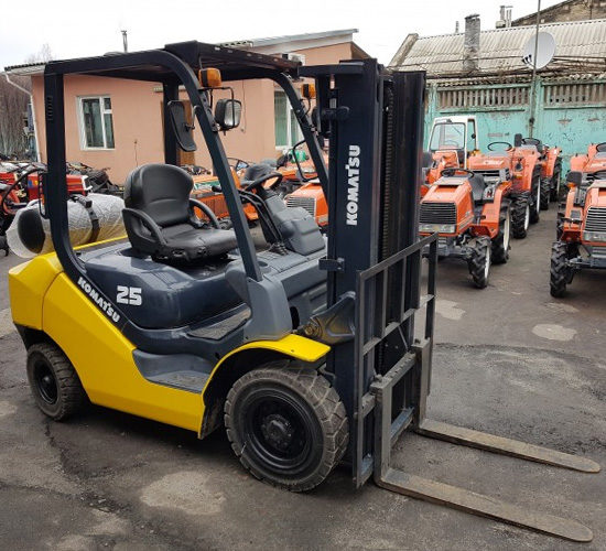
Komatsu FG25T-17 is a 4 × 2 front-end forklift loader designed to carry out loading and unloading, transportation and other types of operations, primarily in warehouses (characterized by limited free space) ... Among its features are strong and reliable design, modern "filling" and excellent technical and operational characteristics
By default, the Komatsu FG25T-17 is equipped with an open cab (devoid of doors and glazing), mounted on a suspension, which features a well-thought-out ergonomics of the operator's workplace. In addition, inside the car is capable of boasting a tilt-adjustable steering column and a comfortable seat with multi-directional adjustments, mechanical suspension and an inertial seat belt.
The front-end loader has the following external dimensions: in length with standard forks, it is 3655 mm (to the front surface of the forks - 2585 mm), of which 1650 mm falls on the center distance, in width along the tires reaches 1150 mm, and in height does not exceed 2110 mm (on the upper mast guard). The ground clearance under the mast of the "Japanese" is 115 mm (in the center of the wheelbase - 160 mm), and its minimum turning radius is 2240 mm. The operating weight of the Komatsu FG25T-17 is 3590 kg, and its rated lifting capacity "rests" at 2500 kg. The total (structurally permitted) mass of the machine is 6090 kg, of which 5420 kg rests on the front axle, and the remaining 670 kg on the rear axle. The Komatsu FG25T-17 is equipped with a 2.1 liter (2065 cubic centimeters) naturally aspirated gasoline unit Nissan K21 with four in-line cylinders, overhead valves and carburetor fuel injection, generating 47 horsepower (34.6 kW) at 2450 rpm and 152 Nm of torque at 1600 rpm. It works in conjunction with a hydromechanical gearbox that sends all the potential to the rear wheels. When moving forward with a load, the car can accelerate up to 18.5 km / h, and without it - up to 19 km / h. For every hour of operation, it "drinks" about 5 liters of fuel, depending on the degree of load. Komatsu FG25T-17 is based on a frame architecture made of high-strength steel grades, on which the cab (on a mechanical suspension) and all the main units and assemblies are located. The front wheels of the loader are clad in pneumatic tires measuring 7.00-12-12PR, and the rear ones - 6.00-9-10PR. The machine is equipped with disc brakes immersed in oil, full hydrostatic power steering and a 58 liter fuel tank.
Rajeev (Tuesday, 22 March 2022 09:27)
Err---5070 means