
ISUZU Fuel system 4HK1, 6HK1

Principle of Operation, 4HK1 Fuel System Diagram, 6HK1, Caution, Diagram 4HK1 Fuel Manifold, 4HK1 Fuel Pump, Fuel Injector, Fuel Cleaning Filter, Function Check, Fuel System Diagnosis,
Maintenance Precautions
Parts of the fuel system, such as parts of fuel injectors, holes and gaps that determine the conditions for the passage of fuel through the channels, are machined with a very high degree of accuracy. Therefore, they are particularly sensitive to the presence of foreign materials, and the admixture of foreign materials can lead to damage to the fuel channels. Therefore, effective measures should be taken to prevent foreign materials from entering the system.
If water absorbents are used in the fuel, they can absorb moisture from the fuel and cause corrosion. Therefore, do not use water absorbers in the fuel tank.
When servicing the fuel system, every effort must be made to ensure that foreign materials do not enter the fuel system.
• Clean fuel lines and adjacent surfaces before starting maintenance.
• Carry out maintenance work with bare, clean hands. Do not use work gloves.
Principle of operation
• After removing the fuel hoses or fuel lines, immediately, carefully wrap the exposed ends of the fuel hoses and fuel lines with vinyl tape.
• When replacing parts (fuel hoses, fuel lines, etc.), do not open the package of new parts until they are installed.
Discard the removed gaskets and O-rings and replace with new ones.
The working process
• When removing the fuel lines, high pressure lines, fuel injectors, fuel pump and fuel manifold, all open spaces must not be left open.
• All bolts and gaskets should be stored in clean boxes with lids to protect them from contamination.
• Leaking fuel may cause a fire. Therefore, after finishing work, collect the spilled fuel, and after starting the engine, check that there is no fuel leakage.
Fuel system diagram
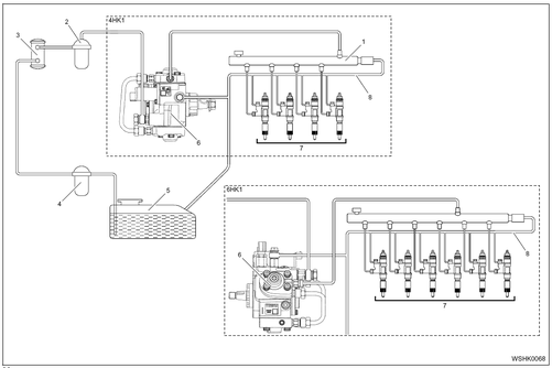
1. Fuel manifold
2. Fuel filter
3. Electromagnetic pump
4. Coarse fuel filter
5. Fuel tank
6. Fuel pump
7. Fuel injector
8. Drain fuel line
Warning:
• Be careful not to allow foreign materials to enter the fuel system because the fuel system components are manufactured to a high degree of precision.
fuel manifold
4HK1
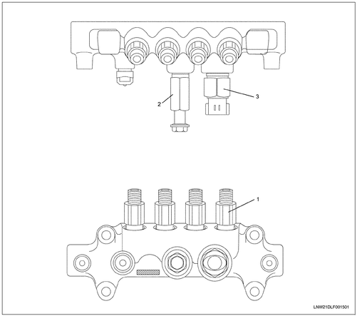
Positions
1. Pulsation damper
2. Pressure relief valve
3. Pressure sensor
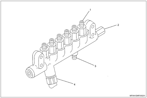
Positions
1. Pulsation damper
2. Pressure relief valve
3. Inlet fitting
4. Pressure sensor
Fuel pump 4HK1

Positions
1. Fuel temperature sensor
2. Suction valve
3. High pressure pipeline
4. Camshaft key
5. Camshaft nut
6НК1

Positions
1. Fuel temperature sensor
2. Suction valve
3. High pressure pipeline
4. Camshaft key
Fuel burner

1. Contact pin
2. Hole for connecting the drain fuel pipeline
3. O-ring
4. High pressure fuel line connection
5. Part number
6. Identification plate
Fuel filter
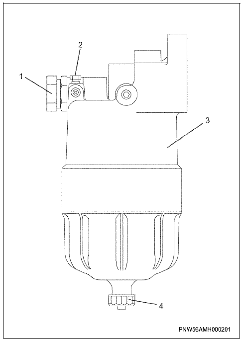
1. Priming pump 2. Air outlet 3. Housing 4. Drain plug
Function test
Air outlet
1. Before starting the engine
A. Install the pan under the fuel filter (under the air outlet plug).
b. Loosen the plug a little and operate the priming pump for at least 20 strokes until fuel begins to flow out from under the plug.
V. Tighten the plug and operate the priming pump for at least 10 strokes until it is filled with fuel. After approximately one minute, loosen the plug and bleed air from the fuel filter. (This process must be repeated at least three times until the release of air from under the cork stops).
d. Tighten the plug securely, and wipe up any spilled fuel. Operate the priming pump (10...15 strokes) until it is filled with fuel and open the fuel to the engine.
2. After starting the engine
A. Start the engine with the starter without depressing the accelerator pedal.
b. After starting, let the engine run at minimum idle speed for 5 seconds.
V. Slowly turn the minimum idle speed control knob clockwise and leave for 3 minutes.
d. Fully depress the accelerator pedal to increase engine speed to maximum. (Repeat these steps several times).
e. Turn the minimum idle speed control knob counterclockwise, and enter the minimum idle speed mode.
Warning:
If the air is not bled completely, engine damage may result. Therefore, the actions after starting the engine must always be carried out.
Draining
The float inside the sump rises as water accumulates. When the float rises and reaches the level of the aluminum part of the body, be sure to drain the water.
The process of draining water
Loosen the air bleed plug at the top of the sump. Then unscrew the drain plug to drain the water from the sump. After draining the water, tighten both plugs securely. Then release the air from the fuel system.
Checking the vacuum in the fuel system
Use this method to measure the vacuum (negative pressure) in the make-up section of the fuel system.
Important:
The fuel gauge/vacuum gauge assembly (gauge (1)) and the fuel gauge/vacuum gauge adapter (adapter (5)) must be cleaned before being connected to the fuel system. Otherwise, the use of contaminated instruments may damage the fuel pump.
1. Disconnect the fuel line from the fuel filter (from the side of the fuel pump).
2. Install adapter.
Special tool
Fuel gauge/vacuum gauge adapter (4NK1, only):
EN-47667
3. Connect the device (1), with hose, to the adapter (3).
Fuel gauge/vacuum gauge, complete:
J-44638
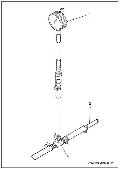
Positions
1. Fuel gauge/vacuum gauge, complete
2. Fuel pipeline (discharge side)
3. Fuel gauge/vacuum gauge adapter (4NK1, only)
4. Loosen the air release plug on the high pressure fuel pump.
5. Manually operate the priming pump on the fuel filter. Operate the pump until air is completely bled from the fuel system.
6. Turn on the engine, and set the minimum idle speed.
7. Note the meter reading (1). If the reading is normal, go to step (8). If the vacuum is greater than the specified value, then there is a malfunction in the fuel system. Perform the operations below.
Standard vacuum value: no more than 17 kPa
(0.17 bar)
• Replace the fuel filter element.
• Check the fuel line. If the fuel supply line is clogged, it must be replaced.
• Remove the inlet fuel line, in front of the filter. Use high pressure compressed air to blow out the pipeline.
Warning:
• Open the fuel filler cap before applying high pressure.
• Do not use this method if the fuel tank is almost full (the fuel level is near or inside the fuel filler neck). Air will blow fuel out of the fuel tank neck.
8. Disconnect the instrument (1) and the hose from the adapter (3).
9. Disconnect the adapter (3).
10. Connect the fuel hose.
11. Manually operate the priming pump on the fuel filter. Operate the pump until air is completely bled from the fuel system.
12. Turn on the engine and set the minimum idle speed.
13. Check the fuel system for fuel leaks.
Special tool

EN-47667
Adapter fitting for fuel gauge/vacuum gauge (4NK1)
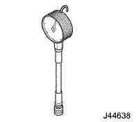
J-44638
Fuel gauge/vacuum gauge, assy