
Eaton Fault Codes. Diagnostic Troubleshooting
Indication of codes of malfunctions
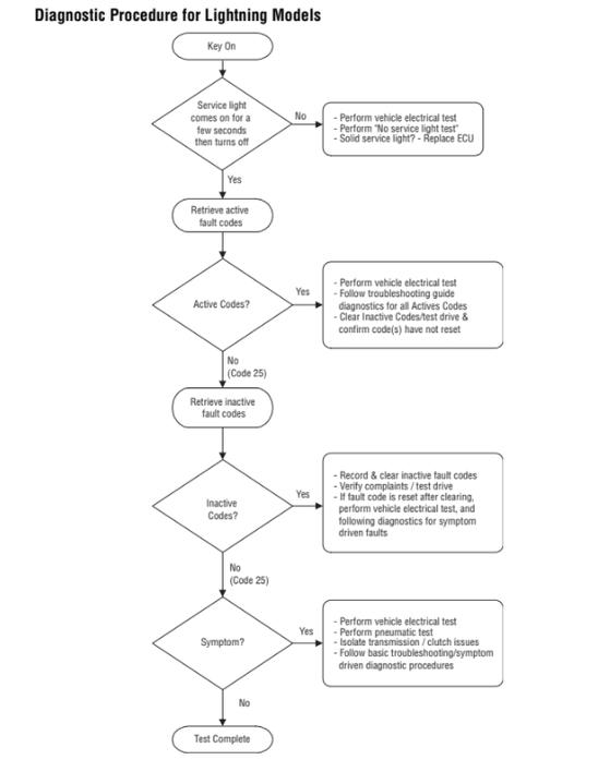
Fault codes are indicated in the system self-diagnosis mode.
Note: A computerized service tool can also be used to display fault codes.
1. Place the gear shift lever in neutral.
2. Apply the parking brake.
3. Switch on the ignition, but without starting the engine. When the engine is running, it is also possible to display codes, but you should not turn on the starter if the engine stalls.
4. Indication of active codes: Initial position - ignition is on. Turn off-turn on the ignition 2 times within 5 seconds, ending in the on position.
After 5 seconds, the diagnostic indicator light starts to indicate flashing two-digit trouble codes. In the absence of malfunctions, the diagnostic indicator lamp displays a flashing code 25 (no codes).
5. Indication of inactive codes: Initial position - ignition is on. Turn off-turn the ignition 4 times within 5 seconds, ending in the on position.
After 5 seconds, the diagnostic indicator lamp starts to indicate flashing two-digit trouble codes. In the absence of malfunctions, the diagnostic indicator lamp displays a flashing code 25 (no codes).
6. Observe the sequence of the diagnostic indicator light and record the codes. The indication is performed with a pause of 1-2 seconds between the codes, and this sequence is repeated after the completion of the indication of all codes.
Reset fault codes
Below is the procedure for discarding all inactive fault codes from the ECU memory. Reset
active fault codes are carried out automatically when the corresponding faults are eliminated.
1. Place the gear shift lever in neutral.
2. Apply the parking brake.
3. Switch on the ignition, but without starting the engine.
4. Initial position - ignition is on. Turn the ignition off and on 6 times within 5 seconds, ending in the on position.
Note: After resetting the codes, the Diagnostic Indicator Lamp will illuminate for 5 seconds.
5. Turn off the ignition and wait until the system is powered off.

FAULT CODES
Code 11 (SID 254, FMI 2.12), System Controller Testing
Component Code: 12 (SID 233, FMI 12) Transmission ECU
Code 12 (SID 233, FMI 12), Transmission ECU Testing
Code 12 (SID 233, FMI 12), Transmission ECU Testing
Component Code: 13 (SID 236, FMI 4.5) Power Relay Coil
Code 13 (SID 236, FMI 4.5), Testing the winding of the power relay
Component Code: 14 (SID 18, FMI 12) Gear Lever
Code 14 (SID 18, FMI 12), Gear Lever Testing
Component Code: 15 (SID 57, FMI 2) Gear Lever Data Circuit
Code 15 (SID 57, FMI 2), Gear Lever Data Circuit Testing
Component Code: 16 (SID 248, FMI 2) Eaton System Circuit (EPL)
Code 16 (SID 248, FMI 2), Eaton System Circuit Testing (EPL)
Component Code: 17 (SID 237, FMI 4) Engine Start Relay Coil
Code 17 (SID 237, FMI 4), Testing the winding of the engine start relay
Component Code: 31 (PID 62, FMI 3.4) Motor Brake Relay Coil
Code 31 (PID 62, FMI 3.4), Motor brake relay coil test
Component Code: 33 (PID 168, FMI 4) Battery Voltage Supply
Code 33 (PID 168, FMI 4), Battery voltage supply test
Component Code: 35 (SID 231, FMI 2.7) Engine Management System Malfunction
Code 35 (SID 231, FMI 2.7), Testing malfunction of the engine management system
Component code: 41 (SID 56, FMI 7) Range enable failure
Code 41 (SID 56, FMI 7), Range Enable Failure Testing
Component code: 42 (SID 61, FMI 7) Divider activation failure testing
Code 42 (SID 6,1, FMI 7), Testing the divider activation failure
Component Code: 43 (SID 35,36, FMI 3,4,5) Range Shift Solenoid Valve
Code 43 (SID 35,36, FMI 3,4,5), Range Shift Solenoid Valve Testing
Component Code: 44 (PID 54, FMI 3,4,5) Inertia Brake Solenoid
Code 44 (PID 54, FMI 3,4,5), Inertia brake solenoid test
Component Code: 46 (SID 37.38, FMI 4.5) Divider Solenoid Valve
Code 46 (SID 37.38, FMI 4.5) Divider Solenoid Valve Testing
Component Code: 51 (PID 60, FMI 2) Range Select Sensor
Code 51 (PID 60, FMI 2), Range Select Sensor Testing
Component Code: 52 (PID 59, FMI 2) Gear Select Sensor
Code 52 (PID 59, FMI 2), Testing the gear selection sensor
Component Code: 53 (SID 34, FMI 2) Reverse Ball Switch
Code 53 (SID 34, FMI 2), Testing the reversing ball switch
Component Code: 56 (PID 161, FMI 2) Input Shaft Speed Sensor
Code 56 (PID 161, FMI 2), Testing the input shaft speed sensor
Component Code: 57 (PID 160, FMI 2) Main Shaft Speed Sensor
Code 57 (PID 160, FMI 2), Testing the main shaft speed sensor
Component Code: 58 (PID 191, FMI 2) Output Shaft Speed Sensor
Code 58 (PID 191, FMI 2), Testing the output shaft speed sensor
Component Code: 61 (SID 39, FMI 5.6) Range Select Motor
Code 61 (SID 39, FMI 5.6) Ranging Motor Test
Component Code: 63 (SID 40, FMI 5.6) Gear Select Motor Test
Code 63 (SID 40, FMI 5.6), Testing the gear selection motor
Component code: 65 (SID 251, FMI 4) Low voltage supply to electric motors
Code 65 (SID 251, FMI 4), Testing low voltage supply of electric motors
Component code: 71 (SID 60, FMI 7) Jammed transmission
Code 71 (SID 60, FMI 7), Testing for jamming of the engaged gear
Component code: 72 (SID 59, FMI 7) Range enable failure
Code 72 (SID 59, FMI 7), Range Enable Failure Testing
Component code: 73 (SID 58, FMI 7) Failure to enable transmission
Code 73 (SID 58, FMI 7), Testing transmission failure
Component code: 74 (SID 54, FMI 7) Lack of synchronization of the initial moment of switching on
Code 74 (SID 54, FMI 7), Testing the lack of synchronization of the initial moment of switching on
Component code: 83 (SID 18, FMI 14) The position of the gear lever is not detected
Code 83 (SID 18, FMI 14), Gear Lever Position Detection Failure Test
Basic System Troubleshooting

Fault Code Table for Lightning Transmission

DESCRIPTION BY CODE


Component Code: 11
(SID 254, FMI 2.12)
System control device
a brief description of
This code indicates an internal malfunction of the ECU of the system control unit.
Fault detection
The system manager checks the program memory each time the ignition is turned on. If the ECU of the system control device detects an error in its memory, then it issues the indicated fault code.
Fault neutralization
This failure will cause a “fall-off in place” condition during driving and a self-diagnosis error on power-up.
Required tool
• Standard hand tools
• Troubleshooting Guide for AutoSelect / AutoShift
Possible reasons
The appearance of this code can be caused by the following:
• Incorrect software configuration
• Malfunction of the ECU of the system control device
Component Code: 12
(SID 233, FMI 12)
Transmission ECU
a brief description of
This code indicates an internal fault in the transmission ECU.
Fault detection
The transmission ECU checks the program memory each time the ignition is switched on.
If the transmission ECU detects an error in its memory, it issues the indicated fault code.
Fault neutralization
This failure will cause a “fall-off in place” condition while driving and an error during system initialization.
Required tool
• Standard hand tools
• Troubleshooting Guide for AutoSelect / AutoShift
Possible reasons
The appearance of this code can be caused by the following:
• Incorrect software configuration
• Faults in the gearbox ECU
Component Code: 13
(SID 236, FMI 4.5)
Power relay coil
a brief description of
This code indicates an electrical problem with the relay that distributes power to the transmission system.
Fault detection
The system controller checks the integrity of the power relay coil. An error is generated when a ground fault or open circuit is detected.
Fault neutralization
This failure will cause a “fall-off in place” condition while driving and an error during system initialization.
Required tool
• Standard hand tools
• Digital multimeter (Volt / Ohm Meter)
• Troubleshooting Guide for AutoSelect / AutoShif t
Possible reasons
The appearance of this code can be caused by the following:
• ECU of the system control device
• Lever wires
• Power relay
Component code: 14
(SID 18, FMI 12)
Gear shift lever
a brief description of
This code indicates an internal malfunction of the gear lever.
Fault detection
When the ignition is turned on and during operation, the system manager continuously evaluates the amount of feedback from the shift lever circuit. If the value of the feedback signal is outside the specified range, then the specified code is issued. This code appears when
short circuit in the battery, short circuit to ground and open circuit.
Fault neutralization
Required tool
• Standard hand tools
• Digital multimeter (Volt / Ohm Meter)
• Troubleshooting Guide for AutoSelect / AutoShift
Possible reasons
The appearance of this code can be caused by the following:
• Malfunction of the gear lever
• System control device
• Vehicle manufacturer's wiring harness