
Hyundai Excavator Error Codes List. DTC
HYUNDAI EXCAVATOR ERROR CODES
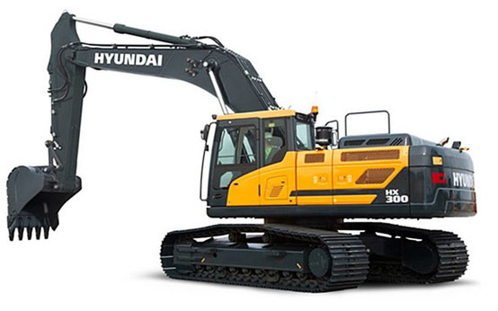
Many models of Hyundai excavators, including older models, have a self-diagnostic system. She is responsible for demonstrating the digital designation of the malfunction on the screen of the working monitor and saving this information in the log. To find out where the problem is localized, you need to decipher the Hyundai excavator error codes
CUMMINS ENGINE ERRORS
Many Hyundai excavators are equipped with a Cummins engine. The designations of engine errors and its systems are identical for all generations and models of machines with this engine.
Here is a list of Cummins error codes. DD - pressure sensor.
HYUNDAI EXCAVATOR ERROR CODES Download
Self-diagnosis system
The microprocessor controller detects problems in the CAPO system caused by electrical and hydraulic faults - and displays them on the LCD (in the form of error codes). This controller is capable of detecting 48 different types of errors. Information from this device (such as engine speed, main pump delivery pressure, battery voltage, hydraulic oil temperature, status of all types of electrical switches) allows the operator to more accurately assess the condition of the machine, and therefore makes it easier to identify the causes of malfunctions.
Examples of error indications:
E0 - actuation of a general protective device, where E is a classification code and 0 means a detailed code
Indoor unit:
A0 - general protective device has been triggered
A1 - the printed circuit board of the indoor unit is faulty
A2 - fan motor blocked
A3 - unacceptable level in the drainage system
A4 - defective heat exchanger
A5 - overheating of the heat exchanger
A6 - fan motor overloaded
A7 - blind drive defective
A8 - current overload (general)
A9 - electronic expansion valve defective
AA - heater overheated
AH - the air filter is clogged
AC - idle running
AJ - performance is incorrectly set (indoor unit)
AE - insufficient water supply
AF - humidifier breakdown
C0 - general sensor malfunction
C3 - the drainage level sensor is faulty
C4 - heat exchanger temperature sensor 1 defective
C5 - heat exchanger temperature sensor 2 defective
C6 - the fan motor is overloaded, the sensor is blocked
C7 - blind drive sensor is out of order
C8 - input current sensor is out of order
C9 - breakdown of the inlet air thermistor
CA - breakdown of the output air thermistor
CH - the pollution sensor is working
CC - breakage of the humidity sensor
CJ - the temperature sensor on the remote control does not work
CE - damage to the radiation sensor
CF - high pressure sensor out of order
Outdoor unit:
E0 - general protective device has been triggered
E1 - the printed circuit board of the outdoor unit is faulty
E3 - HPS (high pressure sensor) is working
E4 - LPS (low pressure sensor) is working
E5 - the compressor motor is overloaded, the overheating relay has tripped
E6 - compressor motor blocked by overcurrent
E7 - fan motor blocked by overcurrent
E8 - current overload (general)
E9 - electronic expansion valve defective
AH - pump blocked
EC - peak water temperature
EJ - additional protection device triggered
EE - critical water level in the drainage system
EF - breakdown of the heat storage unit
H0 - general sensor malfunction
h2 - air temperature sensor defective
h3 - system power supply is faulty
h4 - high pressure sensor defective
h5 - the low pressure sensor is faulty
H5 - overload, compressor stop
H6 - compressor overload, system blocked
H7 - fan overload, system locked
H8 - input voltage drop
H9 - abnormal intake air temperature
HA - abnormal outlet air temperature
HH - water pump blocked
HC - hot water sensor signal
HE - signal from the level sensor of the drainage system
HF - heat storage unit above out of order
F0 - protective system devices No. 1 and No. 2 are functioning
F1 - the protective system device No. 1 is functioning
F2 - the protective system device No. 2 is functioning
F3 - abnormally high temperature of the discharge pipe
F6 - unacceptable temperature in the heat exchanger
FA - unacceptable charge air pressure
FH - oil overheating
FC - unacceptable intake air pressure
FE - invalid oil pressure
FF - invalid oil level indicator
J0 - thermistor defective
J1 - general malfunction of the pressure sensor
J2 - current sensor is faulty
J3 - breakdown of the air discharge pipe temperature sensor
J4 - sensor defective at low pressure saturation point
J5 - thermistor defective on the suction pipe
J6 - thermistor is faulty on the heat exchanger (1)
J7 - thermistor is faulty on the heat exchanger (2)
J8 - thermistor defective on the liquid pipe
J9 - thermistor defective on the gas pipe
JA - the discharge sensor is faulty
JH - temperature sensor ground defective
JC - suction pressure sensor faulty
JE - the oil pressure sensor is faulty
JF - oil level sensor defective
L0 - inverter system faulty
L3 - the temperature of the control box is increased
L4 - the temperature of the heat sink of the power transistor is increased
L5 - short-term overload of a direct current at the output
L6 - short-term overload of alternating current at the output
L7 - total input current high
L8 - electronic thermal relay delay
L9 - safety stop
LA - breakdown of the power transistor
LC - disconnection with the inverter in the outdoor unit
P0 - lack of gas (due to icing of the heat storage system equipment)
P1 - no phase, power supply unbalanced
P3 - overheating of the control unit
P4 - the power transistor (radiator temperature sensor) is out of order
P5 - DC sensor faulty
P6 - sensor for output DC / AC faulty
P7 - input current (in multisystem) is increased
PJ - outdoor unit, performance is incorrectly set
System:
U0 - low pressure in the system due to lack of gas
U1 - phases are incorrectly connected (it is necessary to change phases)
U2 - low voltage in the power supply
U3 - general error in data transmission
U4 - communication failure between outdoor and indoor units
U5 - communication failure between the remote control and the indoor unit
U6 - communication failure between master and slave indoor units
U7 - communication failure between the battery or outdoor units
U8 - communication between control panels is broken
U9 - communication with another system is broken
UA - the parameters of the outdoor unit are incorrectly set
UH - no address entered (outdoor / indoor unit)
UC - the address on the CPU is set incorrectly
UJ - communication with peripheral equipment is broken
UE - communication failure between the CPU and the indoor unit
UF - Incorrect Installation: Wiring / Piping
M1 - defective printed circuit board (central control equipment)
M8 - communication failure with control center equipment
MA - the connection of the control center equipment is broken
MC - dual assignment of the CC equipment address
Other errors:
31 - the humidity sensor of the circulating air is faulty
32 - outside air humidity sensor is faulty
33 - supply air sensor defective
34 - the circulating air temperature sensor is faulty
35 - the outside air temperature sensor is faulty
36 - the temperature sensor of the control panel is faulty
3A - water leakage sensor No. 1 is faulty
3H - water leakage sensor No. 2 is faulty
3C - dew condensation sensor defective
40 - humidifier valve defective
41 - the cold water valve is faulty
42 - the hot water valve is faulty
43 - the cold water heat exchanger is faulty
44 - hot water heat exchanger defective
51 - supply air fan motor overloaded
52 - the circulated air fan motor is overloaded
53 - interruption of the air supply of the inverter
54 - air circulation of the inverter is broken
60 - general error
61 - the printed circuit board is faulty
62 - unacceptable ozone concentration
63 - the pollution sensor is faulty
64 - the sensor of the room temperature control system is faulty
65 - the sensor of the outdoor temperature control system is faulty
68 - the high voltage system is out of order
6A - the damper damper of the system is out of order
6H - door switch open
6C - humidifier element needs to be replaced
6J - high efficiency filter needs replacement
6E - odor removal catalyst requires replacement
6F - the simplified control panel is faulty
Troubleshooting Hyundai excavator fault code / Hyundai excavator error code-9 series Fault code:
101 3 Hydraulic oil temperature sensor line - voltage above normal or short to high voltage
4 Hydraulic oil temperature sensor line - voltage below normal or short circuit to low voltage
105 0 Pressure sensor data working device (idle) above normal
1 Data of the pressure sensor of the working device (idle) below normal
2 data error of the pressure sensor of the working device (idle)
Working device pressure sensor line 4 (idle) - voltage below normal or short circuit to low voltage
108 0 Pressure sensor data when walking (idling) above normal
1 Pressure sensor data when walking (idling) below normal
Error 2-way (idle) pressure sensor
4 running (idle) lines of the pressure sensor - voltage below normal or short circuit to low voltage
120 0 Data of the pressure sensor of the main pump (pump P1) above normal
1 Pressure sensor data of the main pump (pump P1) below normal
2 Data error of the pressure sensor of the main pump (pump P1)
4 Main pump pressure sensor line (pump P1) - voltage below normal or short circuit to low voltage
121 0 Pressure sensor data of the main pump (pump P2) above normal
1 Pressure sensor data of the main pump (pump P2) below normal
2 Data error of the pressure sensor of the main pump (pump P2)
4 Main pump pressure sensor line (P2 pump) - voltage below normal or short to low
122 0 Overload pressure sensor data above normal
1 Overload pressure sensor data below normal
2 Overload pressure sensor data error
4 Overload pressure sensor line - voltage below normal or short circuit to low voltage
123 0 Negative feedback pressure sensor 1 data above normal
1 Negative feedback pressure sensor 1 data lower than usual
2 negative feedback of pressure sensor 1 data error
4 Pressure sensor with negative feedback 1 line - voltage below normal or short circuit to low voltage
124 0 Negative feedback pressure sensor 2 data above normal
1 Negative feedback pressure sensor 2 data is lower than usual
2 negative pressure sensor feedback signal 2 data error
4 Linear feedback pressure sensor 2 - voltage below normal or short circuit to low voltage
125 0 Data of the pressure sensor of the pilot pump (pump P3) above normal
1 Data of the pressure sensor of the pilot pump (pump P3) below normal
2 Pilot pump pressure sensor data error (pump P3)
4 pilot pump pressure transducer line (pump P3) - voltage below normal or short to low
127 0 Boom lift pressure sensor data above normal
1 Boom lift pressure sensor data below normal
2 Boom lift pressure sensor data error
4 Boom lift control pressure sensor line - voltage too low or short to low
133 0 Lever is pointing in / out and bucket is closed. Pilot pressure sensor data above normal.
1 Lever is in / out and bucket is closed. Pilot pressure sensor reading below normal.
2 Lever is in / out and bucket is closed. The pilot pressure sensor data is incorrect.
4 Lever is in / out and bucket accepts pilot pressure sensor line - voltage too low or shorted to low
4 Hydraulic oil temperature sensor circuit - voltage below normal or short to low voltage
1050 working device (idling) higher than normal pressure sensor data Working device (idling) lower than
normal pressure sensor data 2 working device (idle) pressure sensor data error 4 working device (idling)
Pressure Sensor Circuit - Voltage Below Normal or Short to Low Voltage
1080 Walking (idle) above normal pressure sensor data Walking (idling) below normal pressure
sensor data 2 Walk pressure sensor data error (idle) 4 Walk pressure sensor circuit (idle) - voltage
below normal or short circuit to low voltage
Primary pump 1200 pressure sensor data (P1 pump) above normal Main pump pressure (P1 pump)
Sensor data below normal Two main pumps (pump P1) Data error of pressure sensor 4 main pump (pump P1)
Pressure Sensor Circuit - Voltage Below Normal or Short to Low Voltage
1210 Main pump pressure sensor data (P2 pump) above normal Main pump pressure (P2 pump)
sensor data below normal Two main pumps (pump P2) Data error of pressure sensor 4 main pump (pump P2)
Pressure Sensor Circuit - Voltage Below Normal or Short to Low Voltage
1220 Overload of pressure sensor data above normal Overload of pressure sensor data below normal 2
Overload pressure sensor data error 4 Overload pressure sensor circuit - voltage below normal or short circuit to
low voltage
1230: negative feedback pressure sensor data above normal Pressure sensor negative feedback
data below normal Two negative feedback pressure sensors 1 data errors 4 with negative feedback pressure sensor 1
circuit - Voltage below normal or shorted to low voltage
1240 Negative feedback data is higher than normal pressure sensor 2 Negative feedback pressure sensor 2
data below normal Two negative feedback pressure sensors 2 Data error 4 with negative feedback pressure sensor 2
circuit - Voltage below normal or shorted to low voltage
1250 Pilot Pump Pressure Sensor Data (P3 Pump) Above Normal Pilot Pump Pressure (P3 Pump)
sensor data below normal Two pilot pumps (pump P3) Pressure sensor data error 4 pilot pump (pump P3)
Pressure Sensor Circuit - Voltage Below Normal or Short to Low Voltage
1270 Boom Pilot Pressure Sensor Data Exceeded Normal Level Pilot Pressure Sensor Data Increase Significantly
arm below normal 2 large boom pilot pressure sensor data errors raised 4 arm raised pilot pressure sensor circuit -
Voltage below normal or shorted to low voltage
1330 arm inward / outward and displacement pilot pressure sensor data is higher than normal A forearm
to internal / external and bucket pilot pressure sensor data below normal 2 sleeves in / out
and data errors of the pilot-bucket pressure sensor 4 sleeves in / out, and the bucket to close the pilot
Pressure Sensor Circuit - Voltage Below Normal or Short to Low Voltage
The most common errors of converters HYUNDAI N700E:
Error E04 (error E04) - overcurrent. short circuit at the output of the inverter;
Error E05 (error E05) - overheating of the frequency converter;
Error E07 (error E07) - overvoltage;
Error E60 (error E60) - communication error with an external control device;
Error E09 (error E09) - undervoltage;
Error E34 (error E34) - short circuit at the output of the inverter, overcurrent;
Error E13 (error E13) - error of the USP function;
Error E08 (error E08) - malfunction of the EEPROM memory;
Error E12 (error E12) - external fault;
Error E14 (error E14) - short circuit of the inverter output to ground;
Error E17 (error E17) - inverter overload;
Error E20 (error E20) - phase loss at the input of the device;
Error E11 (error E11) - system error of the CPU microprocessor;
Error E22 (error E22) - the safety signal is active;
Error E06 (error E06) - brake resistor error;